N+1 RO trains · 2–40 m³/h · UV and loop monitoring
Hospital Water Filter System — Wards, Sterile Services and Catering
Quick answer
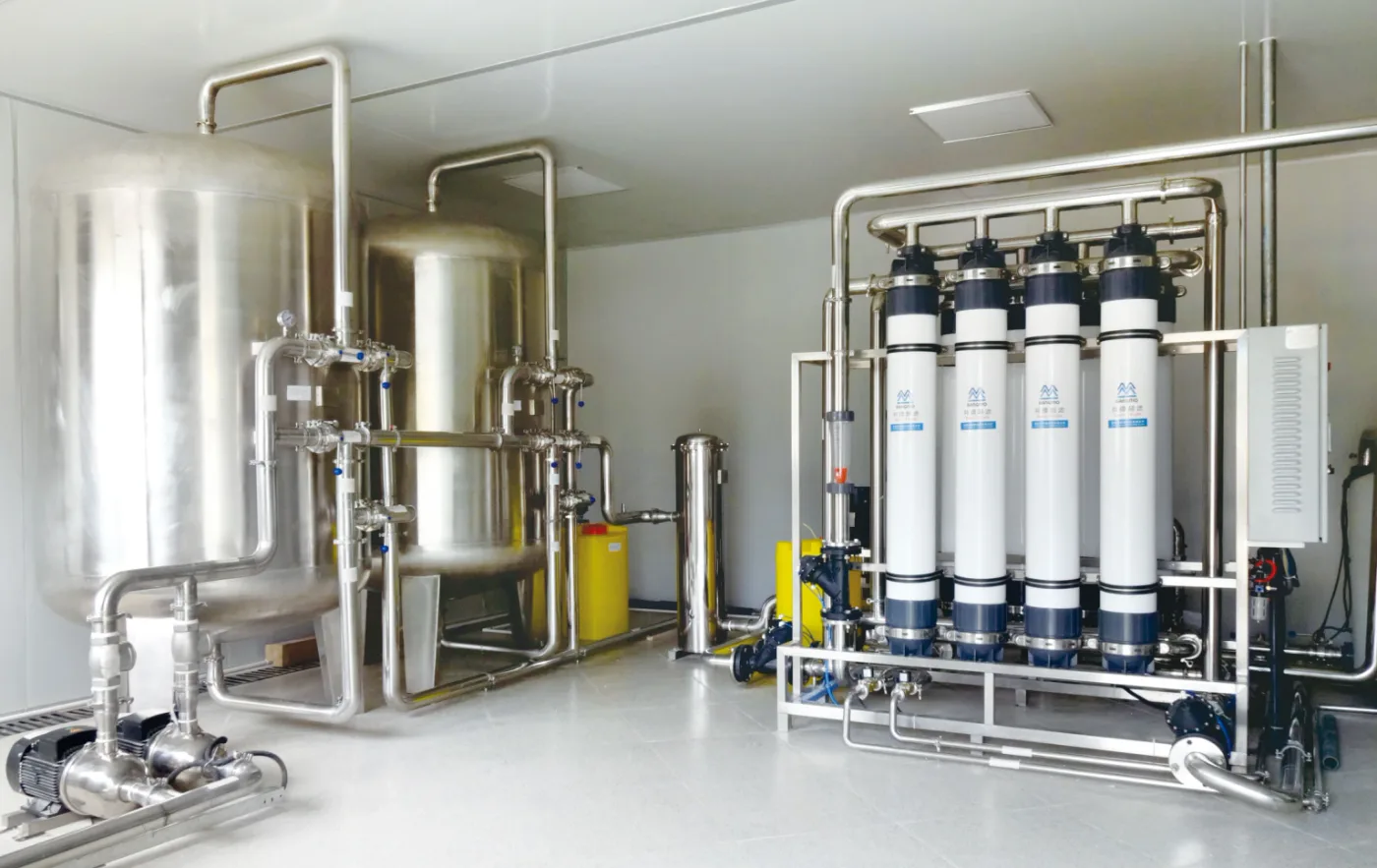
A hospital water system typically combines multimedia and carbon filtration, softening, two-stage RO, UV and a recirculating loop, with duplicate trains for continuous supply. Plan at 400–800 L per bed per day, then separate ward drinking water, sterile services, laundry and catering into dedicated treatment branches.
- Planning demand per bed per day
- 400–800 L Planning demand per bed per day
- Redundant RO trains
- N+1 Redundant RO trains
- RO permeate conductivity
- ≤10 µS/cm RO permeate conductivity
- UV dose after storage
- 30–40 mJ/cm² UV dose after storage
01
What water problems show up in a hospital?
A hospital is not one water user but a group of departments with different quality requirements. Wards need palatable drinking water; sterile services need low-salinity feed for steam and washer-disinfectors; laundry and catering need soft water; laboratories need low-TDS feed for analysers. Treating all of it to one standard either over-treats the laundry or under-treats the sterilizer. The departments also run on different schedules: theatres and sterile services start early, catering peaks at meal times, and wards draw water around the clock, so a single peak figure hides the real operating pattern.
Microbiological safety is the dominant risk. Immunocompromised patients are exposed to water from taps, showers, ice machines and respiratory equipment. Storage tanks, long branches and low-use outlets form biofilm, and stagnation allows bacterial counts to rise even when the incoming mains is clean. Filtration alone does not disinfect a loop; temperature control, recirculation, flushing and UV must work together.
Continuity is the second risk. A plant shutdown affects wards, operating theatres, sterile services, laundry and catering at the same time, and a hospital cannot pause those functions while a pump is replaced. Scale compounds the problem: hardness on steam generators and washer-disinfectors reduces output and increases maintenance intervals, exactly when the department can least afford downtime.
- Biofilm and stagnation in tanks, branches and low-use outlets
- Scale on steam generators and washer-disinfectors
- Single-point failure that stops wards and theatres
- Different quality needs across departments
02
How much water does a hospital use, and how do you size the plant?
Hospital demand is planned per bed. A typical range is 400–800 L per bed per day for the whole building, covering wards, theatres, sterile services, laundry, catering and cleaning. Daily demand equals beds multiplied by litres per bed and by occupancy, normally 0.8–0.9. A 200-bed hospital at 600 L and 85% occupancy uses about 102 m³/day. If the hospital has a large laundry or a dialysis unit, treat those as separate loads; they can dominate the total and should not be averaged into the bed count.
Peak flow equals daily demand multiplied by 1.3–1.6, divided by 20–24 operating hours. For the 200-bed example, peak is about 6–7 m³/h. With N+1 redundancy, install two trains each rated for the peak, so one can be serviced while the other carries the hospital. Drinking water is a smaller separate stream, typically 2–5 L per bed per day, served by its own RO and loop.
| Beds | Typical daily demand | Typical peak flow | Redundant RO trains | Storage |
|---|---|---|---|---|
| 40–60 | 16–36 m³/day | 1.0–2.5 m³/h | 2 × 3 m³/h | 8–12 m³ |
| 80–120 | 32–72 m³/day | 2.5–5.0 m³/h | 2 × 5 m³/h | 12–20 m³ |
| 150–200 | 60–120 m³/day | 4.0–8.0 m³/h | 2 × 10 m³/h | 20–30 m³ |
| 250–400 | 100–240 m³/day | 7.0–16.0 m³/h | 2 × 20 m³/h | 30–50 m³ |
| 500–600 | 200–360 m³/day | 14.0–24.0 m³/h | 2 × 30 m³/h | 50–80 m³ |
Planning values at 400–800 L/bed/day, 80–90% occupancy and 20–24 operating hours. Each train is sized for the design peak; storage covers short excursions above it.
03
Which treatment train does a hospital need?
The building potable stream normally needs multimedia filtration, activated carbon, softening, reverse osmosis, UV and a recirculating loop. Sterile services usually have a dedicated RO train because steam quality and washer-disinfector rinse water are sensitive to conductivity and hardness. Laundry and catering take softened water only. Laboratories may need RO or RO plus EDI for analyser feed. Keep the potable, sterile-services and dialysis systems physically separate, with clearly labelled pipework, so a maintenance error in one loop cannot contaminate another.
Dialysis water is a separate design governed by the applicable renal standard and should be specified with the clinical team; it is not simply a larger drinking-water RO. Where local rules require a residual disinfectant in the potable loop, dose after the storage tank and monitor the residual at the furthest outlet. Every branch should be traceable on a schematic, with sampling points and isolation valves so a section can be taken out without stopping the hospital.
| Department | Quality target | Treatment |
|---|---|---|
| Wards and public areas | Palatable, microbiologically safe | Carbon + RO + UV + loop |
| Sterile services | Low conductivity, low hardness | Softener + two-stage RO + loop |
| Laundry | Soft, low-iron water | Carbon + softener |
| Catering | Soft water, low chlorine | Carbon + softener; RO for drinking |
| Laboratory | Low TDS, stable quality | RO or RO + EDI |
| Dialysis | Applicable renal water standard | Dedicated system, specified separately |
04
Which capacity and configuration fit your hospital size?
The table below converts daily demand into a complete plant. Redundancy drives the layout more than flow does: two trains, two storage compartments and an automatic changeover let maintenance happen without interrupting supply. Storage of 25–40% of daily demand also lets the RO run at a steady rate and ride through a short main interruption. For a hospital with older buildings, verify the incoming main capacity and the riser diameter before selecting the trains; a plant that can produce the flow cannot deliver it through an undersized riser.
| Daily demand | Peak flow | Pretreatment | Main stage | Post-treatment |
|---|---|---|---|---|
| 16–40 m³/day | 1–3 m³/h | Multimedia + carbon + 2–3 m³/h softener | 2 × CK-RO-3000L | UV + divided 10 m³ tank |
| 40–80 m³/day | 3–6 m³/h | Multimedia + carbon + 3–5 m³/h softener | 2 × CK-RO-5000L | UV + divided 20 m³ tank |
| 80–140 m³/day | 6–10 m³/h | Multimedia + carbon + twin 6–8 m³/h softener | 2 × CK-RO-10T | UV + divided 30 m³ tank |
| 140–280 m³/day | 10–20 m³/h | Multimedia + carbon + twin 10–12 m³/h softener | 2 × CK-RO-20T | UV + divided 50 m³ tank |
| 280–400 m³/day | 20–30 m³/h | Multimedia + carbon + twin 15 m³/h softener | 2 × CK-RO-30T | UV + divided 80 m³ tank |
Each train is sized for the full peak so one can be isolated for CIP or repair. Sterile services and dialysis are additional dedicated systems.
05
What are the installation requirements for a hospital plant?
Allow 5 × 4 m for a 100–200 bed plant and 8 × 5 m for 400 beds or more, with 2.5 m clear height and 1.0 m service access around vessels. Provide a floor drain, bunding around chemical and brine areas, a separate ventilated store for antiscalant and cleaning chemicals, and a drainage route that can be neutralised before discharge. Provide a dedicated chemical dosing area with eye wash and spill containment, and keep cleaning chemicals away from the potable storage tank.
Power should be 380 V three phase from a dedicated distribution board, with a standby supply or generator backed feed for at least one RO train, the UV and the control system. Provide a dry contact for each alarm — low pressure, high conductivity, UV failure, tank low level — to the building management system or duty phone. The potable loop should recirculate continuously, with no dead legs and sampling points at the furthest outlet of each branch.
- Plant room 5 × 4 m (100–200 beds), 8 × 5 m (400+ beds)
- Bunding and separate chemical store with ventilation
- 380 V three phase with standby or generator-backed supply
- Alarm dry contacts to BMS or duty phone
- Divided storage so one compartment can be cleaned online
- Sampling points at the furthest outlet of every branch
06
How is a hospital water system maintained?
Daily records should cover pressure, permeate flow, conductivity, UV intensity, tank level, disinfectant residual where used, and any alarm. Weekly tasks include softener salt and hardness checks, loop temperature review and flushing of low-use outlets. Quarterly work includes tank and loop sanitation, microbiological sampling at defined points, and inspection of UV quartz sleeves.
Membrane replacement should be planned from performance trends, not from a fixed date: rising feed pressure, falling permeate flow or rising conductivity at constant temperature all point to fouling or scaling. Keep a spare set of cartridges, a spare UV lamp and a rebuild kit for the softener valve on site. Any change to the loop layout should be added to the schematic and the sampling plan, or the monitoring programme will slowly stop matching the building. Trend the normalised flow and salt consumption monthly; a slow drift is easier to correct than a failure discovered during a ward round.
| Item | Interval | Action |
|---|---|---|
| Operating log | Daily | Pressure, flow, conductivity, UV, tank level |
| Softener | Weekly | Salt level, hardness test, regeneration check |
| Low-use outlets | Weekly | Flush until temperature or residual is stable |
| Tank and loop | Quarterly | Sanitise, flush and take samples |
| UV lamp | 9,000–12,000 h | Replace lamp; clean quartz sleeve |
| RO membranes | Performance-based | CIP or replace when normalised flow falls 10–15% |
Specifications
Delivery and service — typical ranges
| Item | Typical range |
|---|---|
| Standard skid lead time | 15–30 days after drawing approval |
| Containerized / turnkey lead time | 30–60 days after drawing approval |
| Warranty | 12–18 months from shipment |
| Factory testing | Hydrostatic pressure test and trial run with water before packing |
| Documentation | General arrangement drawing, P&ID, test record, O&M manual and spare-parts list |
| Packaging | Seaworthy plywood crate, or container for containerized plants |
| Installation support | Remote guidance as standard; on-site engineer available on request |
| Operator training | 1–2 days at commissioning, covering operation, CIP and consumables |
| Spare parts | Recommended two-year list quoted separately with the equipment |
| Payment terms | Typically 30% deposit and 70% before shipment; confirmed in the quotation |
| Minimum order | 1 unit |
| Loading port | Guangzhou or Shenzhen, China |
| Power supply | 220/380/415/440 V, 50/60 Hz; confirmed on order |
| Ambient temperature | 5–40 °C |
| Enclosure protection | IP54 for indoor skids; higher IP available on request |
| Certification | CE and ISO 9001; model-specific test reports on request |
Typical industry ranges for planning. Final scope, commercial terms and lead time are confirmed in the quotation.
FAQ
Frequently asked questions
Questions buyers actually ask during sizing and quotation. Answers match the specifications above.
01 Can one RO train serve the whole hospital?
02 How is continuous supply maintained?
03 How is Legionella risk controlled?
04 Is dialysis water the same as hospital drinking water?
05 How much RO capacity does a 200-bed hospital need?
06 Do we need softening before the RO?
07 What monitoring is required?
08 What space and power does the plant need?
Next step
Send your water analysis, get a factory quotation
Tell us the source water, TDS, hardness, iron and daily demand. Factory engineers reply with a flow rate, process train and budget range within one working day.